Humminbird 300TX User Manual
Browse online or download User Manual for Sports and recreation Humminbird 300TX. Humminbird 300TX User Manual
- Page / 28
- Table of contents
- BOOKMARKS
Summary of Contents
INSTALLATION INSIDE THE HULL INSTALLATION INSIDE THE HULL INSTALLATION Inside the hull installation requires the mount system and control head be in
INSTALLATION INSIDE THE HULL INSTALLATION 3. Power up the Control Head. 4. Run the boat at various speeds and water depths while observing the scr
INSTALLATION CONTROL HEAD INSTALLATION CONTROL HEAD INSTALLATION Step One - Determine Where to Mount Begin the installation by determining where to
INSTALLATION CONTROL HEAD INSTALLATION and one amp fuse (not included) for the protection of the unit (Figure 21). Humminbird is not responsible for
INSTALLATION CONTROL HEAD INSTALLATION Step Five - Assembling the Connector Holder 1. Insert the cable connectors into the connector holder. The ca
INSTALLATION TEST THE INSTALLATION TEST THE INSTALLATION Testing should be performed with the boat in the water, however you can initially confirm b
Using the 300TX Actual depth capability depends on factors such as bottom hardness, water conditions, and transducer installation. Units will typica
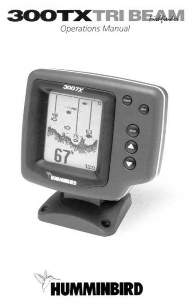
What You See On-Screen Your 300TX uses a 128 x 64 matrix FSTN LCD display. This display provides outstanding viewability in all light conditions o
Wave action also affects the bottom depiction. The information drawn is a distance measurement, so if the boat is moving up and down over flat bott
species. The signal intensity is “normalized” for depth so that a small fish close to the boat does not appear as a large fish symbol. ID+ adds an a
INSTALLATION PREPARATION PARTS SUPPLIED PARTS SUPPLIED Before installing your new Humminbird fishfinder, please ensure the following parts are inclu
screen indefinitely. Once you release the menu button, the screen will time out. Once a menu times out, it is still considered the active menu. Pre
In murky or muddy water, it is often helpful to reduce the sensitivity. This prevents the display from being cluttered with sonar returns from debri
Zoom. Zoom is similar to Depth Range because it controls the range of information displayed on screen. Zoom, however, allows selection of ranges ben
Fish Alarm. The Fish Alarm alerts you to the presence of fish, or other targets not connected to the bottom. The Fish Alarm has three different sett
Units Depth/Speed. Only available on metric versions, the Units Depth/Speed function allows the user to select the units of measurement for the dept
switch is changed. Only if the transducer is faulty do you need to manually identify the transducer in the menu. The 300TX can work with an older du
To use the Diagnostic feature, select the Diagnostic feature on the start-up menu on the initial screen. Diagnostic can also be accessed through the
Diagnostic can be used to evaluate the health of the batter by showing the current voltage. Total Time. The total time category indicates the total
Maintenance Your 300TX is designed to provide years of trouble free operation with virtually no maintenance. Follow these simple procedures to ensu
INSTALLATION PREPARATION INSTALLATION OVERVIEW Determining How to Mount the Transducer Your Humminbird fishfinder includes a standard transducer. Th
INSTALLATION PREPARATION ALTERNATE MOUNTING METHODS ALTERNATE TRANSDUCERS AND MOUNTING METHODS Your Humminbird fishfinder comes with everything nece
INSTALLATION PREPARATION TRANSDUCER EXCHANGE TRANSDUCER EXCHANGE Other transducers are available as replacements for the standard transducer. You ma
INSTALLATION TRANSOM INSTALLATION Do not begin this transducer installation until you read the Installation Preparation in the Operation Guide. This
INSTALLATION TRANSOM INSTALLATION • If the propeller(s) is (are) forward of the transom, it may be impossible to find an area clear from turbulence,
INSTALLATION TRANSOM INSTALLATION Step Four - Mount the Transducer to the Transom 1. Apply silicone sealant to the mounting holes drilled into the
INSTALLATION TRANSOM INSTALLATION Step Six - Route the Cable There are several ways to route the transducer cable to the to the area where the contr
Related products and manuals for Sports and recreation Humminbird 300TX
 (19 pages)
 (116 pages)
© 2020, manymanuals.com. All rights reserved. | 0.170 s |
 Manymanuals.com
 Manymanuals.de
 Manymanuals.fr
 Manymanuals.it
 Manymanuals.pl
 Manymanuals.cz
 Manymanuals.es
 Manymanuals-pt.com
Comments to this Manuals